

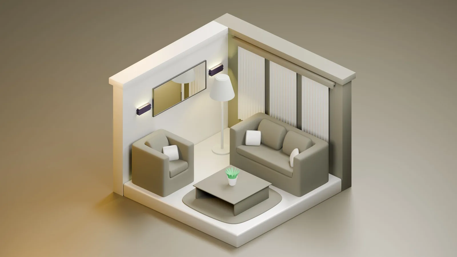
An axonometric drawing is a parallel projection that shows a building’s plan, height and depth in a single image, with no vanishing point. Because the lines stay parallel and the axes keep a fixed scale, measurements can be read straight off the drawing. Isometric, dimetric and trimetric are its three types.
Plan, section, elevation. Three flat drawings, each holding one part of the story. An axonometric folds all of them into one measurable image, which explains why the technique outlived the drafting board and still turns up in competition boards, construction details and BIM exports.
What Is an Axonometric Drawing?
An axonometric drawing is an orthographic parallel projection. The object is rotated away from the picture plane so that three faces show at once, while the projection rays stay parallel to each other. Nothing converges. A wall six metres back is drawn at the same scale as a wall sixty metres back, and a scale rule still works on the finished sheet.
Perspective does the opposite. It bends lines toward vanishing points to imitate the eye, so the image feels real but cannot be measured. That trade is the whole point of an axonometric view: you give up optical realism and get dimensional truth back.
The idea is old. Chinese scroll painters used parallel projection centuries before European art settled on perspective, and the historian Auguste Choisy later turned the worm’s eye axonometric into a scholarly instrument for reading Roman construction, a lineage traced in academic surveys of axonometry. What changed in the twentieth century was who used it, and why. That story sits inside the broader evolution of architectural visualization, from hand drawing to CAD to AI rendering.
📌 Did You Know?
Isometric projection was formalised in 1822 by William Farish, a Cambridge professor, in a paper called “On Isometrical Perspective” written for machine drawing rather than buildings. Architecture adopted it a full century later. Axonometry became fashionable in the 1920s through the Bauhaus and De Stijl, and Theo van Doesburg’s axonometric designs caused a stir when they were exhibited in Paris in 1923.
The Three Types of Axonometric Projection
Every axonometric projection is defined by one variable: how much each of the three axes is foreshortened. That single choice produces the three types recognised in technical drawing.
Isometric Projection
Isometric means equal measure. All three axes are foreshortened by the same amount, which puts the projected axes 120 degrees apart. In practice you draw the two ground axes at 30 degrees above the horizontal and keep verticals vertical, which is exactly what a 30/60 set square is for. One scale serves height, width and depth.
The true foreshortening factor is roughly 0.82, and almost nobody applies it. Drawing at full scale is the studio convention, and it yields an image about 22 percent larger than a strict isometric projection. Nothing breaks, provided every axis gets the same treatment.
Dimetric Projection
Dimetric keeps two axes at one scale and gives the third another. It exists because isometric’s even-handedness sometimes works against you: when a single facade carries the design, you want that face read cleanly and the depth pushed back. The ISO setup places the axes at 7 degrees and 42 degrees, with two axes at full scale and the third at half.
Trimetric Projection
Trimetric gives every axis its own angle and its own scale. It is the general case, and both isometric and dimetric are special instances of it. By hand it is punishing, since three separate scales have to be tracked at once. On screen it costs nothing, which is why most axonometric viewport captures out of Rhino or Revit are technically trimetric. The camera lands where you orbit it, not on a textbook angle.
📐 Technical Note
The reference document is ISO 5456-3:1996, Technical drawings, Projection methods, Part 3: Axonometric representations, confirmed as current in its most recent review. It sets out isometric, dimetric and oblique (cavalier and cabinet) representations, and it fixes the dimetric axes at 7 degrees and 42 degrees with a scale ratio of 1 : 1 : 0.5. Its scope covers all types of technical drawing, so any office standard that cites it applies to architectural sheets too.
Where Plan Oblique and Elevation Oblique Fit In
Walk into most architecture schools and “axo” means something else: a plan oblique. The plan is rotated, usually 45/45 or 30/60, then every height is pulled straight up. The plan keeps its true shape and true scale, so it can be traced directly off the working drawing.
Strictly, that is an oblique projection rather than a true axonometric, because the projection rays meet the picture plane at an angle. ISO files cavalier and cabinet obliques under axonometric representations anyway. The vocabulary is genuinely muddled, and the drawing does not care what you call it, but your consultant might.
⚠️ Common Mistake to Avoid
Axonometric and isometric are not synonyms. Isometric is one member of the axonometric family, sitting alongside dimetric and trimetric. The confusion becomes expensive when someone asks for “an axo” and receives a 30 degree isometric instead of the 45 degree plan oblique they had pictured. Ask which convention is expected, or name it in the drawing title. Ten seconds of clarity saves a redraw.
Axonometric Projection Types at a Glance
The table below summarises the angles and scales behind each method, and what each one is actually good for.
| Projection | Typical axis angles | Scale on the three axes | Best used for |
|---|---|---|---|
| Isometric | Ground axes at 30 degrees, 120 degrees between axes | Equal on all three (0.82 true, drawn at 1:1) | Equal weight on every face, fast grid work |
| Dimetric (ISO) | 7 degrees and 42 degrees | 1 : 1 : 0.5 | Giving one facade priority over the others |
| Trimetric | All three differ, set per view | All three differ | Chosen camera angles in 3D software |
| Plan oblique (planometric) | Plan rotated 45/45 or 30/60, verticals vertical | Plan true, heights true | Interiors, urban blocks, reusing the plan directly |
| Cavalier and cabinet oblique | Receding axis at 45 degrees | Cavalier 1:1:1, cabinet halves the receding axis | Details where one face must stay undistorted |
How to Draw an Axonometric View Step by Step
Drawing an axonometric by hand takes six moves, and the order matters more than the drafting skill.
- Choose the projection and the corner. Isometric for equal emphasis, plan oblique when the plan carries the information. Rotate the plan so the corner you want to explain faces the viewer.
- Set the axes. For an isometric, run the two ground axes at 30 degrees above horizontal. For a plan oblique, rotate the plan 45/45 or 30/60 and leave verticals vertical.
- Lay in the base. In a plan oblique you trace the rotated plan as it is. In an isometric the plan has to be rebuilt along the 30 degree axes, point by point.
- Pull the heights. Take verticals up from every corner at the same scale as the base, then close the top by drawing parallels back to the two ground axes.
- Cut, slice or explode. Drop a section plane through the massing, lift roof and floor layers apart along one shared axis, or remove a wall to open the interior.
- Build hierarchy last. Three line weights (outline, plane change, surface), one shadow direction, hatch only what needs reading. Dimensions can then be taken straight off the drawing.
💡 Pro Tip
A plan oblique is the fastest axonometric to build by hand because the plan stays true: rotate the drawing, tape it under your sheet, and pull heights straight up. An isometric offers no such shortcut. Its plan is foreshortened, so it must be redrawn on the 30 degree axes before a single height goes up. Skipping that step is the classic studio error, and it shows up as a plan that no longer matches the drawing it was measured from.
Setting Up an Axonometric View in SketchUp, Rhino and Illustrator
The camera setting decides everything. If the projection is left on perspective, the result is not an axonometric, whatever the view is labelled. In SketchUp, Camera and then Parallel Projection removes the vanishing points and puts line lengths back on scale, and pairing it with the Iso standard view gives a true isometric. Rhino, Revit and ArchiCAD carry the same switch under different names.
From there, the drawing is an export. Turn off annotation layers, hide the grid, capture the parallel view as a PNG, and treat that line work as your base. It is the same clean export logic that makes a SketchUp scene export or a Rhino viewport capture usable downstream, and an axonometric view exported from AutoCAD holds enough depth information to be rendered rather than just printed. Most modelling tools export a viewport in one step, so the axo becomes an asset instead of a dead end.
In Illustrator, a flat plan or elevation can be pushed onto an isometric plane without a plugin: scale it vertically to 86.6 percent, shear it 30 degrees, then rotate it 30 degrees, flipping the signs depending on which face you are building. Three passes and the drawing stands up.
💡 Pro Tip
Before exporting from any 3D model, check that the projection is genuinely parallel and not a narrow field of view standing in for one. A five degree perspective camera reads as flat on screen and still bends verticals once the image is blown up on an A1 board. For a repeatable isometric, set the camera by numbers (45 degrees around the vertical axis, then 35.26 degrees down) rather than orbiting by eye, or your axes will never align with a grid you overlay later.
When an Axonometric View Earns Its Place
The exploded axonometric is the workhorse. Pulling floors, structure, envelope and services apart along a single axis explains an assembly in one image, which is why architects reach for it to describe construction sequences and layered systems. ArchDaily‘s survey of disassembled axonometry as a design tool shows the range, from conceptual diagrams to construction details.
Sectional axonometrics do the same job for interiors, cutting the box open while keeping every room measurable. Worm’s eye views, drawn from below, read ceilings and structure the way a plan never can. At urban scale, a plan oblique of a city block keeps the street pattern true while the massing rises out of it.
There is a presentation argument too. A photorealistic render shows what a space will look like; an axonometric explains why it works. That difference matters when you are presenting a scheme to a client with no technical background, and it is the same logic behind choosing stylized drawings over photorealistic renders at the right stage of a project. Most strong presentations carry both.
Where to Go From Here
Your Next Step: Take a plan you are already working on, rotate it 45 degrees, tape it under a fresh sheet and pull every height straight up. You will have a working plan oblique in twenty minutes, and it will tell you more about your massing than another hour spent orbiting a model.
Drawing conventions vary between offices, national standards and software defaults. Confirm the projection and scale expected on your project before issuing a drawing.
Frequently Asked Questions
What is the difference between axonometric and isometric drawing?
Axonometric is the family of parallel projections that show three faces of an object without a vanishing point. Isometric is one member of that family, the one where all three axes are equally foreshortened and sit 120 degrees apart. Dimetric and trimetric are the other two members.
Is an axonometric drawing to scale?
Yes. Lines parallel to the three axes hold a constant scale, so dimensions can be measured directly from the sheet. Diagonals and any line that is not parallel to an axis cannot be measured, which is the one trap in an otherwise measurable drawing.
What angle is used for an axonometric drawing?
An isometric uses 30 degrees for the two ground axes, giving 120 degrees between the projected axes. A plan oblique normally rotates the plan 45/45 or 30/60 and keeps verticals vertical. The ISO dimetric convention uses 7 degrees and 42 degrees.
How do you draw an exploded axonometric?
Build the standard axonometric first, then separate the layers along one axis, usually the vertical. Keep the spacing between layers consistent, align every part on the same axis lines, and add thin dashed leaders so a reader can see how the pieces go back together.