Quick answer: Three different things get sold as AutoCAD to 3D model AI. Plan readers rebuild a generic room model from what your drawing looks like. Underlay tools put the DWG behind a canvas so something can be drawn on top. CAD to BIM conversion produces a real model and is still mostly done by people. Only the third gives you geometry you can build from.
The phrase covers a wide range of outcomes, and the gap between them is where the disappointment happens. Someone uploads a DWG expecting the drawing to become a model, and gets back a tidy little house that shares the room layout and nothing else.
This guide separates the three, says what each one is genuinely good for, and covers the case that turns out to be most common: you did not need a model, you needed an image.
Three Different Things Called AutoCAD to 3D
Plan reading
The largest group. You upload a plan and the tool identifies walls, doors and windows from the image, then rebuilds them as its own parametric objects. Tools in this category, including Cedreo and Coohom, come from residential design rather than from CAD, and it shows in what they assume.
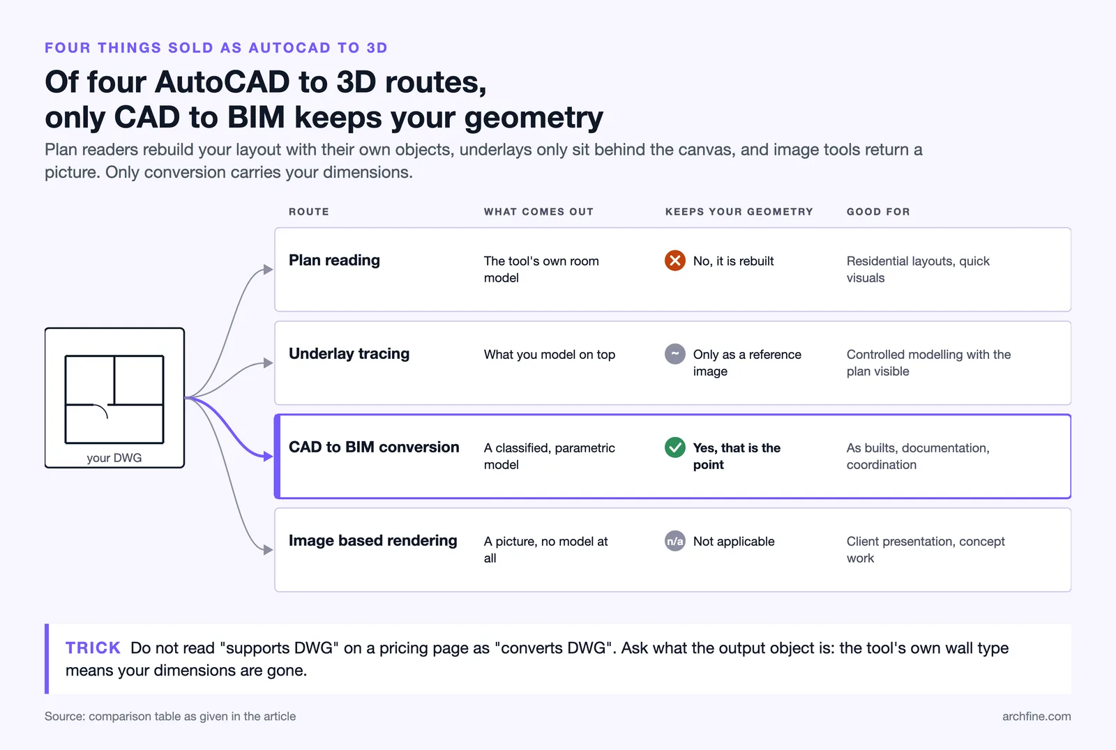
The important thing to understand is that your geometry is not converted. It is read, interpreted, and replaced. A wall in the result is the tool’s wall object at the tool’s default thickness, positioned where it thinks your wall was. That is fine for a marketing visual of an apartment layout. It is not fine if your dimensions are contractual.
Underlay tracing
Several tools accept DWG and DXF, which reads as support for your file format. Often what they accept is an underlay: the drawing sits behind the drawing canvas as a reference, and walls get placed on top of it. Some of that placement is assisted, some is manual.
This is a legitimate and useful workflow. It is also not conversion, and the distinction matters when you are estimating how long a job will take. Importing a DWG as a background is a two-minute operation. Modelling on top of it is not.
CAD to BIM conversion
The real thing, and the one people usually mean. Turning a 2D DWG into an intelligent model means interpreting geometry, classifying each element as the building component it represents, embedding parametric data and keeping disciplines coordinated.
Automation helps with the simple parts. Full automation is not currently realistic for actual projects, which is why CAD to BIM is sold as a service with modellers attached rather than as a button. AI-assisted tools detect planes and repeated geometry well; deciding that a particular rectangle is a load-bearing wall with a fire rating is still a person’s job.
⚠️ Common Mistake to Avoid
Reading “supports DWG” on a pricing page as “converts DWG”. Ask instead what the output object is. If the answer is the tool’s own wall type rather than your geometry, you are in the plan reading category, and the model will not carry your dimensions through.

What Your Drawing Has to Contain
Every approach above degrades sharply on a messy file, and the failure is quiet: you get a model, it just does not match. The drawing characteristics that decide the outcome are fairly consistent.
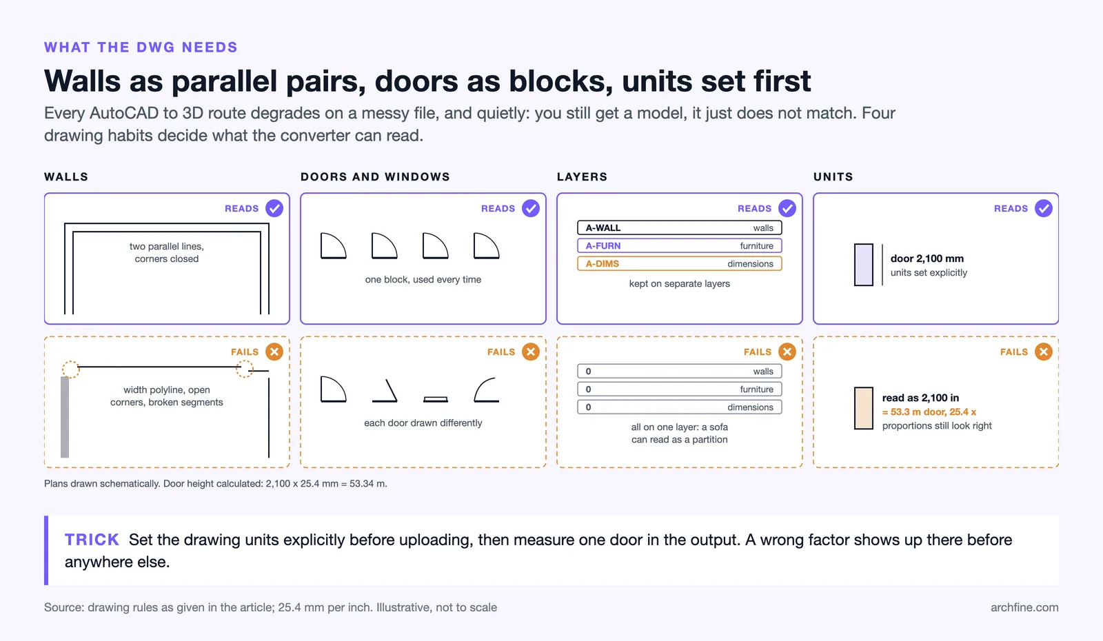
Walls need to read as walls. Two parallel lines at a consistent offset are recognisable. A wall drawn as a single polyline with a width, or as a hatch boundary, or as four separate segments that do not meet at the corner, is not. Closed geometry matters more than tidy geometry.
Doors and windows need to be blocks, and preferably consistent ones. A tool looking for openings finds them by pattern. Twelve door symbols drawn twelve slightly different ways read as twelve unrelated objects. This is the one case where AutoCAD’s own Smart Blocks features pay off directly before you export anything, because converting loose geometry into consistent blocks is exactly what they do.
Layers need to separate. If walls, furniture, dimensions and hatching share a layer, everything is one object as far as the reader is concerned. Furniture in particular gets misread as partition walls surprisingly often.
📐 Technical Note
Check drawing units before uploading anything. A plan drawn in millimetres and interpreted as inches produces a building at roughly twenty-five times scale, and because the proportions stay correct the error is easy to miss until you check a door height. Set units explicitly rather than relying on the file to declare them.

Where It Works and Where It Falls Over
Plan reading handles orthogonal residential layouts well. Rectangular rooms, standard door widths, walls that meet at right angles, a single floor. That is the training distribution and results inside it are genuinely good.
It falls over on the things architecture is actually made of. Curved and angled walls get approximated or straightened. Split levels and mezzanines flatten, because a plan does not carry height and the tool assumes one storey. Anything unusual in section, which is to say most projects worth visualising, is invisible to a process that only ever saw the plan.
There is also a quieter limit. These tools infer height from convention rather than from your drawing. Ceiling heights come from a default. Window head heights come from a default. If your project is interesting precisely because those are not standard, the model will silently normalise it.
| Approach | What comes out | Keeps your geometry | Good for | Falls over on |
|---|---|---|---|---|
| Plan reading | The tool’s own room model | No, it is rebuilt | Residential layouts, quick visuals | Curves, levels, non-standard heights |
| Underlay tracing | What you model on top | Only as a reference image | Controlled modelling with the plan visible | It is modelling, so it costs modelling time |
| CAD to BIM conversion | A classified, parametric model | Yes, that is the point | As-builts, documentation, coordination | Cost and turnaround, since people do it |
| Image based rendering | A picture, no model at all | Not applicable | Client presentation, concept work | Anything that needs measuring |
💡 Pro Tip
Test any tool on a drawing you already know the answer to before you use it on live work. Take a project you modelled by hand, run the plan through, and compare a few dimensions. Ten minutes on a known file tells you more than any feature list, and it tells you specifically how the tool behaves on the way your office draws.

How to Check the Output in Five Minutes
Whatever produced the model, the review is the same, and doing it in a fixed order catches the failures that hide behind a good-looking render.
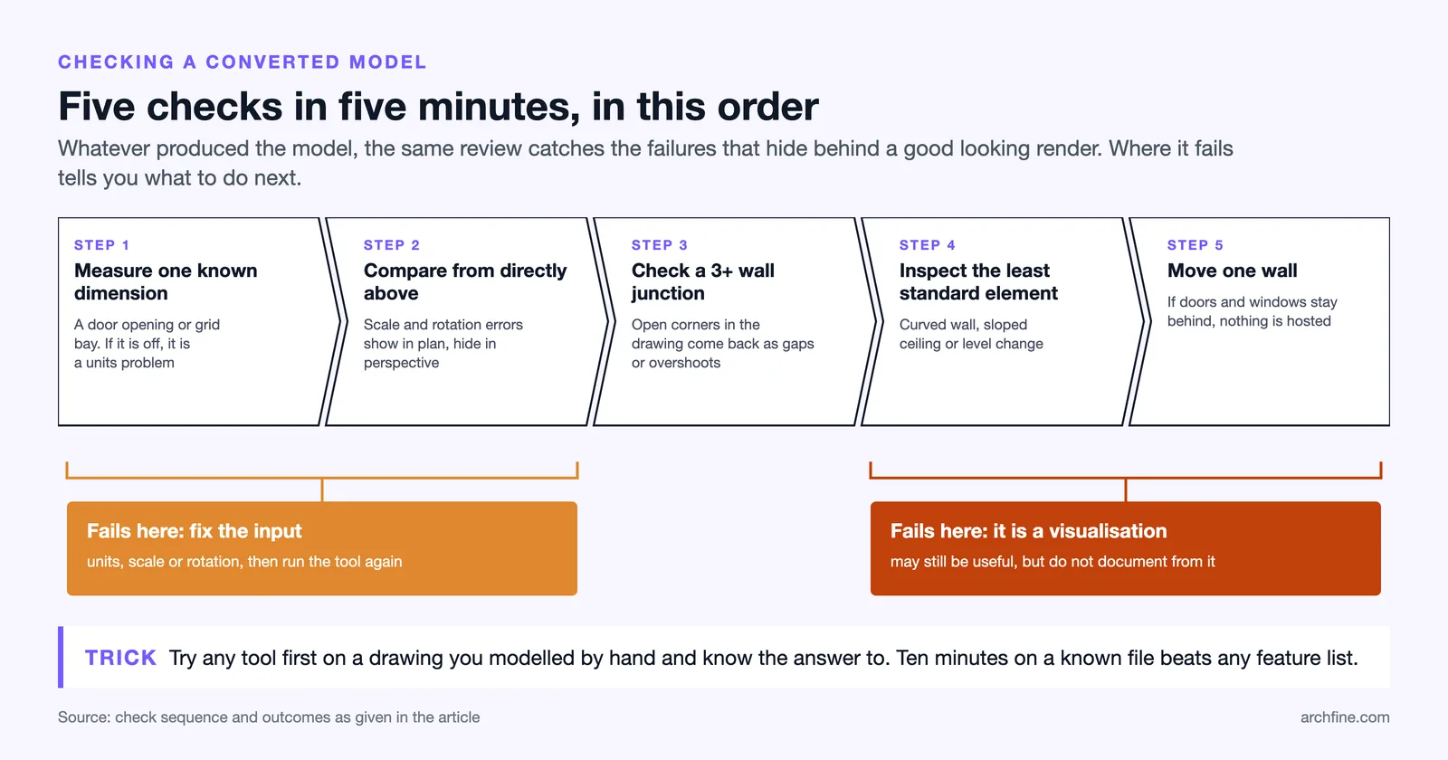
- Measure one known dimension. A door opening or a structural grid bay. If it is off, everything downstream is off by the same factor and you have a units problem rather than a modelling one.
- Look at the plan from directly above and compare it to the original. Scale and rotation errors are obvious from the top and nearly invisible in perspective.
- Check a corner where three or more walls meet. Junctions are where recognition breaks first, and a corner that did not close in the drawing produces a gap or an overshoot here.
- Find the least standard element in the project and look only at that. If there is a curved wall, a sloped ceiling or a level change, the result there tells you whether the tool understood the building or the convention.
- Move one wall. If the windows and doors in it stay behind, the elements are not hosted and the model is a set of shapes rather than something you can edit.
Failing step one or two means going back and fixing the input. Failing four or five means the output is a visualisation, which may still be useful, but it is not a model you should document from.
What Conversion Does Not Give You
Even when geometry comes across correctly, a model is more than shapes, and the part that does not transfer is the part that makes a model worth having.
A drawing carries no element classification. Nothing in a DWG says that a particular rectangle is an exterior wall rather than an interior partition, and nothing says it is load-bearing. That distinction is what drives structural coordination, fire strategy and cost. Whatever produces the model has to decide it, and the decision comes from either a convention or a person.
A drawing carries no parametric data. Fire ratings, U-values, material specification, manufacturer references: none of it exists in the lines. A converted model looks complete and is empty behind the surface, which is a specific trap because it passes visual review.
A drawing carries no relationships. In a real model a window hosts in a wall and moves with it. In a converted one it can sit at the same coordinates without being attached, so the first time somebody moves that wall the window stays behind.
This is why CAD to BIM pricing is quoted per drawing with a level of development attached rather than per file. The geometry is the cheap part.

The Question Worth Asking First
Before choosing between these, it is worth checking whether you need a model at all. In practice the request behind “turn my AutoCAD plan into 3D” is usually one of two things, and they have very different answers.
If something downstream consumes the geometry, you need a model. Clash detection, quantity take-off, documentation, energy analysis, anything a contractor will build from. Accept that this is CAD to BIM work with the cost that implies, and treat automation as something that reduces the modelling hours rather than eliminating them.
If what you need is a picture for a client, a competition board or a planning submission, a model is an expensive detour. You would build geometry, light it, set a camera and render, in order to arrive at an image. Image-based tools skip the middle entirely: you export the view you already have and work from that. The workflow, including what the export should contain, is covered in AutoCAD AI rendering, and the same logic applied to plans specifically is in our guide to the rendered floor plan.
ArchFine sits in that second group. It works from an exported view rather than from a model, which is why it fits an AutoCAD workflow that has no 3D in it, and the free tier is enough to test whether the output holds on your own drawings.
✅ Key Takeaways
- Plan reading rebuilds your layout as the tool’s own objects. Your dimensions do not survive.
- DWG support often means underlay, not conversion. Ask what the output object is.
- Real CAD to BIM conversion is a service with modellers attached, not a button.
- Clean layers, closed walls and consistent door blocks decide the result more than the tool does.
- Check units first. A millimetre plan read as inches fails silently because proportions stay correct.
- If the goal is an image rather than geometry, skip the model entirely.

Frequently Asked Questions
Can AI convert an AutoCAD drawing to a 3D model?
Partly. Tools can read a plan and produce a 3D representation of the layout, but that representation is usually built from their own objects rather than converted from your geometry. For a model that carries your dimensions and classifications, the work is CAD to BIM conversion and still involves people.
Does AutoCAD have a built-in 2D to 3D AI feature?
No. AutoCAD’s Autodesk AI features cover block detection and markup interpretation. There is no built-in command that generates a 3D model from a 2D plan.
Why does my converted model have the wrong wall thickness?
Because the tool used its own default rather than reading yours. Plan readers place their own wall type where they detect a wall, so thickness comes from the tool’s settings, not from your drawing.
Will it handle curved or angled walls?
Usually poorly. Recognition is trained on orthogonal residential layouts, so curves get approximated and unusual angles get straightened. Check any non-rectangular part of the plan before trusting the output.
What file should I upload, DWG or PDF?
DWG or DXF if the tool genuinely reads geometry, because layer information survives and helps it separate walls from furniture. If the tool works from the image, a clean high-resolution PDF export with annotation layers turned off often produces a better read than the raw drawing.
Is it faster than modelling by hand?
For a simple orthogonal plan, yes. For anything with level changes, curves or non-standard heights, the correction time frequently exceeds the modelling time, which is why testing on a known file first is worth the ten minutes.